Connecting the Switch to the Router (28.4)
Most local networks have only one router. This router will be the gateway router and all hosts and switches on your network must be configured with this information. This topic explains how to configure the default gateway on hosts and switches.
Default Gateway for a Host (28.4.1)
For an end device to communicate over the network, it must be configured with the correct IP address information, including the default gateway address. The default gateway is only used when the host wants to send a packet to a device on another network. The default gateway address is generally the router interface address attached to the local network of the host. The IP address of the host device and the router interface address must be in the same network.
For example, assume an IPv4 network topology consisting of a router interconnecting two separate LANs. G0/0/0 is connected to network 192.168.10.0, while G0/0/1 is connected to network 192.168.11.0. Each host device is configured with the appropriate default gateway address.
In Figure 28-2, if PC1 sends a packet to PC2, then the default gateway is not used. Instead, PC1 addresses the packet with the IPv4 address of PC2 and forwards the packet directly to PC2 through the switch.
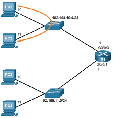
Figure 28-2 PC1 sending a packet to PC2
What if PC1 sent a packet to PC3? As shown in Figure 28-3, PC1 would address the packet with the IPv4 address of PC3, but would forward the packet to its default gateway, which is the G0/0/0 interface of R1. The router accepts the packet and accesses its routing table to determine that G0/0/1 is the appropriate exit interface based on the destination address. R1 then forwards the packet out of the appropriate interface to reach PC3.
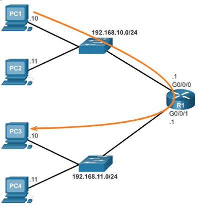
Figure 28-3 PC1 sending a packet to PC3
The same process would occur on an IPv6 network, although this is not shown in the topology. Devices would use the IPv6 address of the local router as their default gateway.
Default Gateway on a Switch (28.4.2)
A switch that interconnects client computers is typically a Layer 2 device. As such, a Layer 2 switch does not require an IP address to function properly. However, an IP configuration can be configured on a switch to give an administrator remote access to the switch.
To connect to and manage a switch over a local IP network, it must have a switch virtual interface (SVI) configured. The SVI is configured with an IPv4 address and subnet mask on the local LAN. The switch must also have a default gateway address configured to remotely manage the switch from another network.
The default gateway address is typically configured on all devices that will communicate beyond their local network.
To configure an IPv4 default gateway on a switch, use the ip default-gateway ip-address global configuration command. The ip-address that is configured is the IPv4 address of the local router interface connected to the switch.
Figure 28-4 shows an administrator establishing a remote connection to switch S1 on another network.
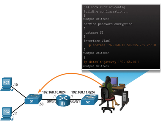
Figure 28-4 Administrator establishing a remote connection to switch S1
In this example, the administrator host would use its default gateway to send the packet to the G0/0/1 interface of R1. R1 would forward the packet to S1 out of its G0/0/0 interface. Because the packet source IPv4 address came from another network, S1 would require a default gateway to forward the packet to the G0/0/0 interface of R1. Therefore, S1 must be configured with a default gateway to be able to reply and establish an SSH connection with the administrative host.
Note:
Packets originating from host computers connected to the switch must already have the default gateway address configured on their host computer operating system.
A workgroup switch can also be configured with an IPv6 address on an SVI. However, the switch does not require the IPv6 address of the default gateway to be configured manually. The switch will automatically receive its default gateway from the ICMPv6 Router Advertisement message from the router.
Syntax Checker – Configure the Default Gateway (28.4.3)
Use this syntax checker to practice configuring the default gateway of a Layer 2 switch.
Refer to the online course to complete this Activity.
Packet Tracer – Build a Switch and Router Network (28.4.4)
This Packet Tracer Tutored Activity includes a hinting system and a built-in tutorial. You will connect the devices, configure the PCs, configure the router, configure the switch, and verify end-to-end connectivity.
Refer to the online course to complete this Packet Tracer.
Packet Tracer – Troubleshoot Default Gateway Issues (28.4.5)
In this activity, you will complete the following objectives:
- Verify Network Documentation and Isolate Problems
- Implement, Verify, and Document Solutions
Refer to the online course to complete this Packet Tracer.