Shielded Twisted-pair (STP) (30.3.4)
Shielded twisted-pair (STP) provides better noise protection than UTP cabling. However, compared to UTP cable, STP cable is significantly more expensive and difficult to install. Like UTP cable, STP uses an RJ-45 connector.
STP cables combine the techniques of shielding to counter EMI and RFI, and wire twisting to counter crosstalk. To gain the full benefit of the shielding, STP cables are terminated with special shielded STP data connectors. If the cable is improperly grounded, the shield may act as an antenna and pick up unwanted signals.
The STP cable shown in Figure 30-13 uses four pairs of wires, each wrapped in a foil shield, which are then wrapped in an overall metallic braid or foil.
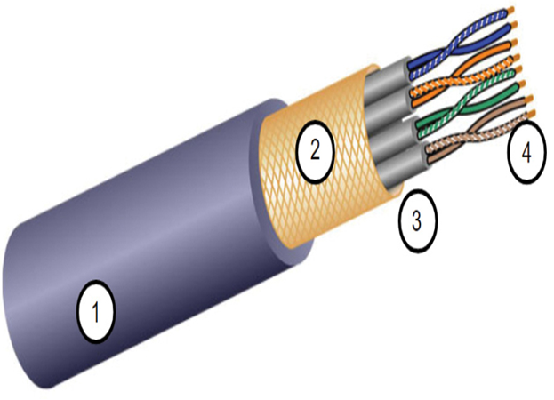
Figure 30-13 STP Cable
The numbers in Figure 30-13 identify some key features of STP cable:
1. Outer jacket
2. Braided or foil shield
3. Foil shields
4. Twisted pairs
Coaxial cable, or coax for short, gets its name from the fact that there are two conductors that share the same axis. As shown in the figure, coaxial cable consists of the following:
• A copper conductor is used to transmit the electronic signals.
• A layer of flexible plastic insulation surrounds a copper conductor.
• The insulating material is surrounded in a woven copper braid, or metallic foil, that acts as the second wire in the circuit and as a shield for the inner conductor. This second layer, or shield, also reduces the amount of outside electromagnetic interference.
• The entire cable is covered with a cable jacket to prevent minor physical damage.
There are different types of connectors used with coax cable. The Bayonet Neill–Concelman (BNC), N type, and F type connectors are shown in Figure 30-14.
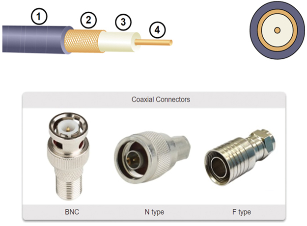
Figure 30-14 Coaxial Cable and Connectors
The numbers in Figure 30-14 identify some key features of coaxial cable:
1. Outer jacket
2. Braided copper shielding
3. Plastic insulation
4. Copper conductor
Although UTP cable has essentially replaced coaxial cable in modern Ethernet installations, the coaxial cable design is used in the following situations:
• Wireless installations — Coaxial cables attach antennas to wireless devices. The coaxial cable carries radio frequency (RF) energy between the antennas and the radio equipment.
• Cable internet installations — Cable service providers provide internet connectivity to their customers by replacing portions of the coaxial cable and supporting amplification elements with fiber-optic cable. However, the wiring inside the customer’s premises is still coax cable.
Check Your Understanding – Copper Cabling (30.3.6)
Refer to the online course to complete this Activity.
Copper media has some inherent issues. Twisting the internal pairs of the copper media, as used in UTP, is a low-cost solution to improve some of the cabling performance. This section will further explore UTP cabling.
Properties of UTP Cabling (30.4.1)
In the previous topic, you learned a bit about unshielded twisted-pair (UTP) copper cabling. Because UTP cabling is the standard for use in LANs, this topic goes into detail about its advantages and limitations, and what can be done to avoid problems.
When used as a networking medium, UTP cabling consists of four pairs of color-coded copper wires that have been twisted together and then encased in a flexible plastic sheath. Its small size can be advantageous during installation.
UTP cable does not use shielding to counter the effects of EMI and RFI. Instead, cable designers have discovered other ways that they can limit the negative effect of crosstalk:
• Cancellation — Designers now pair wires in a circuit. When two wires in an electrical circuit are placed close together, their magnetic fields are the exact opposite of each other. Therefore, the two magnetic fields cancel each other and also cancel out any outside EMI and RFI signals.
• Varying the number of twists per wire pair — To further enhance the cancellation effect of paired circuit wires, designers vary the number of twists of each wire pair in a cable. UTP cable must follow precise specifications governing how many twists or braids are permitted per meter (3.28 feet) of cable. Notice in Figure 30-15 that the orange/orange white pair is twisted less than the blue/blue white pair. Each colored pair is twisted a different number of times.
UTP cable relies solely on the cancellation effect produced by the twisted wire pairs to limit signal degradation and effectively provide self-shielding for wire pairs within the network media.
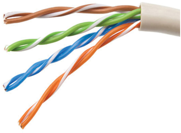
Figure 30-15 Different Number of Twists in Each UTP Pair